Robotic Welding Best Practices for High-Volume Manufacturing
High-volume manufacturing rewards consistency and punishes drift. A welding cell that runs beautifully on Monday morning can turn into a scrap generator by Thursday afternoon if fit-up shifts, consumables wear unevenly, or a fixture starts letting parts float a millimeter out of position. That is the real challenge with robotic welding. The robot itself is usually the most consistent part of the process. Everything around it determines whether that consistency turns into good welds or highly repeatable defects.
Shops that move from manual welding to robotic welding often expect the biggest gains to come from speed. Speed matters, but in practice the bigger wins usually come from stability, labor utilization, and the ability to hold quality over long production runs. A well-designed robotic cell can weld the same joint geometry with far less variation than even a strong manual welder over a ten-hour shift. The trick is that the cell has to be built and managed like a system, not like a robot dropped into a booth.
I have seen high-volume lines where the welding robot got blamed for issues that had nothing to do with path accuracy. The actual root causes were warped incoming blanks, spatter buildup on locating pins, poor gas coverage caused by damaged nozzles, or HMI programming so clumsy that operators bypassed alarms just to keep parts moving. Best practices start with accepting a simple truth: repeatable welding requires repeatable part presentation, repeatable clamping, repeatable process settings, and repeatable maintenance.
Start with the joint, not the robot
A surprising number of robotic welding problems begin in product design. Engineers approve a joint that a skilled hand welder can handle, then later ask automation to produce it at high speed with minimal variation. The robot exposes weaknesses in the design because it cannot improvise around poor access, variable gaps, or joints that need constant visual correction.
For high-volume work, the best joint is not always the one that uses the least material. It is usually the one that tolerates realistic variation while still allowing good torch access and clean fixturing. A fillet weld tucked behind a flange might look fine on a print, but if the contact tip is forced into an awkward angle and the gas nozzle loses proper shielding, the line will pay for that decision every shift.
Joint design should be reviewed with production, welding engineering, and fixture design in the room. Look closely at gap tolerance, edge condition, expected distortion, and whether the sequence can be automated without creating trapped stresses. If laser cutting leaves a rough edge or plasma cutting creates dross, the robotic cell will feel it immediately in arc stability and wetting behavior. In high-volume environments, tiny design compromises multiply into thousands of parts and hundreds of operator interventions.
It helps to think in terms of process windows. If the parts arrive with a gap variation of plus or minus 0.8 mm, and your chosen weld process only performs comfortably within plus or minus 0.4 mm, the robot is not the problem. The process window is too tight for the reality of your upstream manufacturing.
Fixture quality is process quality
Most experienced integrators eventually arrive at the same conclusion: the fixture deserves as much engineering attention as the robot path. In many cells, it deserves more.
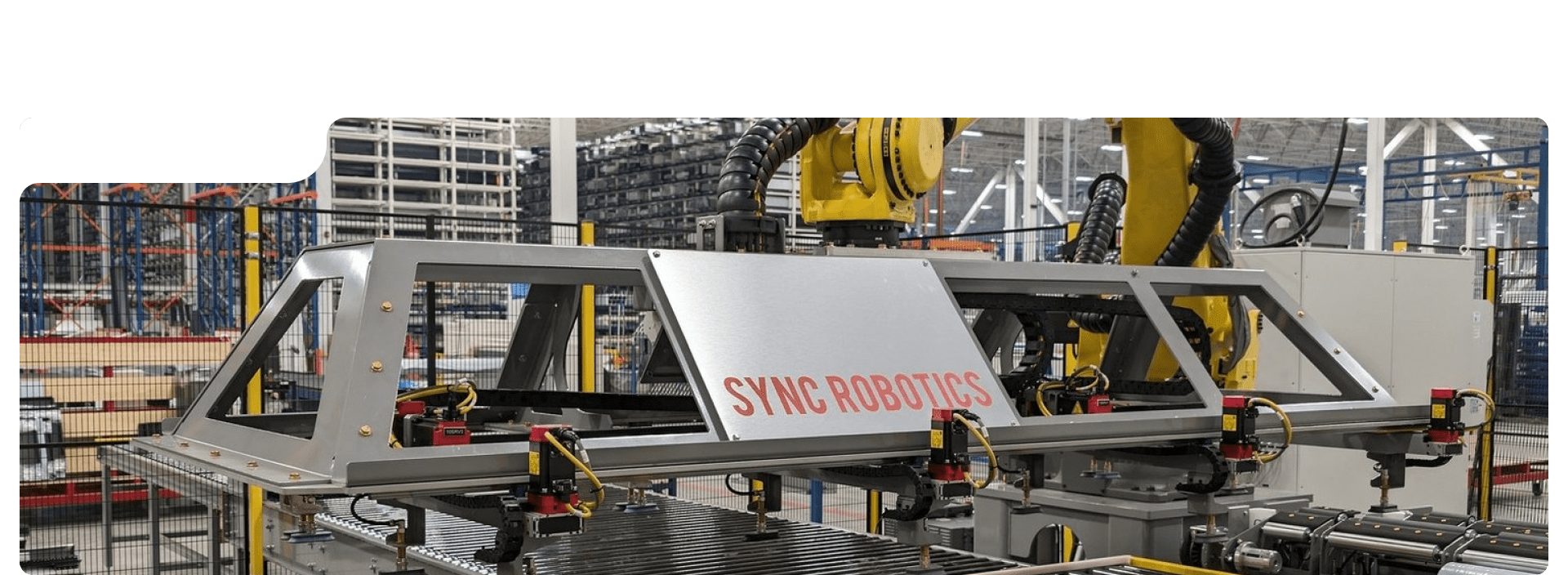
A robot can return to the same taught position within a very small tolerance. If the part is not in the same place every cycle, the robot will faithfully miss the joint every cycle. Good fixtures locate parts positively, clamp them securely, and avoid over-constraining them in ways that lock in distortion. They also let the operator load parts quickly without fighting the tooling.
For high-volume work, fixture design should answer four practical questions. First, can the part be loaded the same way every time, even by a tired operator on second shift? Second, do the clamps actually hold the part in welding position, or do they merely press it in a direction that changes once heat goes in? Third, does spatter have a place to go, or will it accumulate on locators and alter part position over time? Fourth, can maintenance access the wear points without disassembling half the cell?
Simple details matter. Hardened and replaceable locator pins last longer and preserve dimensional consistency. Open fixture architecture sheds spatter better than tight pockets. Pneumatic clamps with confirmation sensors give better process assurance than purely manual clamps when takt time is aggressive. On thin-gauge assemblies, backing bars or heat sinks can stabilize the joint and reduce burn-through. On heavier fabrications, fixture compliance sometimes helps more than brute force. If a fixture is too rigid in the wrong places, weld shrinkage will move the part in ways that create residual stress and downstream dimensional problems.
This is also where end of arm tooling enters the conversation. On welding cells, end of arm tooling is not only about the torch package. It can include part grippers for load-unload robots, sensors for part verification, wire cutters, nozzle cleaners, and dress packs that preserve cable life. If a system combines robotic welding with machine tending or secondary handling, the end effector strategy becomes even more important. A gripper that picks a subcomponent from a CNC automation station and presents it to a weld fixture has to maintain orientation within the same tolerance logic as the welding process. A sloppy handoff upstream often appears downstream as a welding defect.

Part variation will find every weak assumption
High-volume manufacturing creates a false sense of confidence when the first few runs go smoothly. Then a new lot of stamped parts arrives, or a supplier changes a bending die, and the weld quality slips. The cell did not change, but the conditions around it did.
That is why validation should go beyond a short runoff using ideal sample parts. Run the cell with parts from different lots, different shifts, and realistic material conditions. Include borderline but acceptable incoming variation. If the process can only produce quality welds with perfect parts, it is not ready for production.
Seam tracking, through-arc sensing, touch sensing, and vision can all help, but they are not substitutes for discipline in upstream processes. They are tools for managing variation, not excuses for allowing it to grow unchecked. Touch sensing, for example, is useful for locating a weld start point on a formed assembly, but if every part requires significant path offset because the fixture or incoming components are unstable, the line is carrying hidden risk. Cycle time expands, maintenance rises, and eventually quality escapes.
The best shops set control limits for critical incoming dimensions and correlate those dimensions to weld outcomes. If porosity spikes when a flange angle drifts beyond a certain range, that relationship should be documented and acted on. Welding quality becomes easier to control when it is tied to measurable conditions rather than operator intuition alone.
Tune the welding process for the production rate you actually need
It is tempting to chase maximum deposition and minimum cycle time from day one. That usually backfires. A robotic welding process should first be made stable, then made fast.
Short circuit GMAW may be fine for thin parts and positional tolerance, while pulsed MIG often offers a better mix of arc stability, lower spatter, and appearance on many steel and stainless applications. On thicker material, spray transfer may be suitable if joint position and heat input allow it. The right choice depends on metallurgy, thickness, access, cosmetic requirements, and the economics of rework.
For high-volume production, process tuning should consider not just bead shape and penetration, but also the less glamorous factors that drive uptime: nozzle fouling rate, tip life, wire feeding consistency, gas consumption, and how sensitive the process is to part gap changes. A parameter set that produces beautiful welds in the lab can become expensive if it burns through contact tips every few hours or throws enough spatter to force frequent cleaning pauses.
In one production cell I reviewed, the team had increased travel speed by roughly 18 percent, which looked like a success on paper. A month later, actual throughput was barely improved because unplanned stoppages from spatter-related torch maintenance had climbed so sharply. Slowing the weld slightly, adjusting gas flow and stickout discipline, and revising the anti-spatter regimen cut downtime enough that net daily output went up. High-volume efficiency is never just about arc-on seconds.
Sequence matters too. Weld order affects distortion, access, and how much correction the fixture must absorb. On some assemblies, alternating sides or stitching strategic areas before final passes can keep the part flatter. On others, a continuous path reduces starts and stops enough to justify the heat pattern. There is no universal answer, which is exactly why process development has to be done on production-intent parts and fixtures.
Program for maintainability, not just motion
Robotic programmers often get judged by cycle time and path smoothness. In production, maintainability matters almost as much. A beautifully optimized path that only one programmer understands becomes a liability at 2:00 a.m. When a torch crash forces a recovery.
Clear program structure saves money. That includes sensible frame definitions, reusable routines, comments that describe process intent, and parameter naming that operators and technicians can understand. HMI programming plays a bigger role here than many teams realize. If the interface is confusing, operators start guessing. Guessing leads to bypassed interlocks, incorrect recipe selection, and poor fault recovery.
Good HMI programming should make the right action obvious. Recipe names should match actual part families used on the floor. Alarm text should describe the problem in plain language, not cryptic tag names. Recovery screens should guide users through safe restart steps without requiring tribal knowledge. Maintenance counters for nozzles, reamers, wire feed components, and filters should be visible and credible. If the HMI says a torch clean is due every 5,000 cycles, but the actual process needs attention every 2,000, operators will stop trusting the screen.
A practical programming standard also helps when a cell is part of a broader automated line. Many plants now blend robotic welding with CNC automation, machine tending, and part transfer systems. In those environments, program handshakes, state logic, and fault handling need to be consistent across equipment. If the weld cell uses one style of reset logic and the adjacent machine tending station uses another, fault recovery becomes slower and riskier than it needs to be.
One useful discipline is to test every common fault as if you are training a new operator who has never seen the line. Simulate a missing part, low wire condition, failed clamp confirmation, and interrupted cycle. If recovery takes too many screens or unclear prompts, revise it before launch.
The torch package deserves daily attention
Consumables are where many high-volume welding cells quietly lose money. Contact tips, nozzles, diffusers, liners, drive rolls, and gas components rarely fail dramatically at first. They degrade gradually, and that gradual decline shows up as increased spatter, arc wander, porosity, or inconsistent starts.
The line between preventive care and over-maintenance is real. Replacing every consumable too early wastes money. Waiting too long creates scrap and downtime. The right interval comes from production data, not assumptions. Track tip life by wire type, amperage range, duty cycle, and part family. Track reamer effectiveness. Check whether anti-spatter application is helping or contaminating the process.
Under many conditions, a disciplined torch cleaning station pays for itself quickly, especially in carbon steel applications with moderate to high arc-on time. But those stations still need oversight. Reamers dull. Spray systems clog. If the cleaning unit is not maintained, the cell simply automates a false sense of protection.
The symptoms that usually signal a torch package slipping out of control are easy to recognize once a team starts watching for them:
- Arc starts become less consistent, especially after breaks or shift changes.
- Spatter accumulates faster on the nozzle and nearby fixtures.
- Operators increase touch-ups or wire clipping between cycles.
- Gas-related defects appear intermittently rather than continuously.
- Tip changes become reactive instead of scheduled.
When these signs appear, resist the urge to tweak weld parameters first. Check the physical condition of the torch, cable routing, feeder tension, and gas delivery. Software often gets blamed for hardware drift.
Uptime comes from routines, not heroics
Plants with strong robotic welding performance usually have ordinary, disciplined maintenance habits. Plants that struggle often rely on a few highly capable people who rescue the process repeatedly. Heroics feel impressive, but they are expensive and fragile.
A high-volume cell should have a daily and weekly care routine that operators and maintenance technicians can execute without ambiguity. That routine does not need to be long. It needs to be consistent. A ten-minute check done every shift is worth more than a heroic three-hour intervention every few weeks.
A practical daily focus often includes these items:
- Verify locator cleanliness and clamp function.
- Inspect the torch, nozzle, and cable dress for wear or damage.
- Confirm wire feed path and gas supply condition.
- Check for spatter buildup on sensors, reamers, and fixture surfaces.
- Review alarm history for repeating faults, not just active ones.
Alarm history is especially valuable. Repeated minor faults usually point to wear or process instability before they become a major stop. If a clamp confirmation drops out twice a day, or a wire feed alarm appears once per shift, treat that pattern as meaningful. High-volume manufacturing gives you enough data to see trends early if someone is looking.
Mean time between failure and mean time to repair are useful measures, but only if they are tied to actual causes. A cell that stops frequently for a thirty-second sensor wipe has a different improvement path than a cell that runs for days and then loses four hours to a failed torch cable. Both may have similar uptime numbers in a report, yet require different engineering responses.
Train operators to manage the process, not just push the button
The best robotic welding cells still depend on attentive operators. In fact, as automation rises, operator judgment often becomes more valuable, not less. Their role shifts from direct weld execution to part loading, process monitoring, first-level troubleshooting, and quality awareness.
Training should reflect that reality. Operators need to understand what a good joint fit-up looks like, how to recognize early consumable wear, what normal arc behavior sounds like, and when a fixture condition is drifting. They do not need to become welding engineers, but they should know enough to stop a bad trend before it becomes a pallet of scrap.
Visual standards help, especially for mixed-model production. So do brief work instructions at the point of use, provided they are kept current. The strongest cells also create a clean escalation path. If an operator sees intermittent porosity, they should know whether to check shielding gas, inspect the nozzle, quarantine incoming parts, or call maintenance first. Confusion at that moment costs more than any training session.
Cross-training matters when robotic welding is tied into adjacent systems such as machine tending or CNC automation. A line operator may need to understand how a dimensional issue from a machined component affects fixture seating at the weld station. These are not separate islands. The health of one process becomes visible in the next.
Quality control should be built into the cell, not bolted on later
End-of-line inspection catches defects after value has already been added. In high-volume manufacturing, that is too late. The cell itself should contain enough process assurance to reduce the chance of making bad parts in the first place.
That may include clamp confirmation, part presence sensing, weld current or voltage monitoring, wire feed verification, and periodic destructive validation outside the cell. Some plants go further with vision checks or bead inspection, but those tools work best when they support a stable process rather than trying to police a chaotic one.
Traceability can also be worthwhile, especially for safety-critical parts. Linking a weld recipe, timestamp, alarm history, and operator login to each lot gives engineering a much better chance of solving recurring issues. The value of traceability rises when production volume is high enough that small defect rates still represent significant absolute numbers.
Do not overlook post-weld dimensional checks. A part can have acceptable bead appearance and still fail downstream assembly due to heat distortion. If the next process is robotic assembly, machine tending into a secondary operation, or a machining step in a CNC automation cell, weld distortion becomes a throughput issue for the entire line, not just a quality issue for the welding area.
When integration is the real bottleneck
Some of the most interesting robotic welding problems are not welding problems at all. They are integration problems. A plant may automate welding successfully, then discover that part flow, upstream machining, or downstream handling cannot support the cell’s cadence.
This happens often when welding is linked with CNC automation. A machined component arrives with https://www.syncrobotics.ca/about-us/ excellent dimensional repeatability, but the palletization strategy introduces orientation errors. Or a machine tending robot and a welding robot compete for floor space and maintenance access because the layout was optimized for simulation, not for real people carrying tools and replacement parts.
Cycle balancing becomes important here. If the weld cell is significantly faster than its feeder process, buffer strategy matters. If it is slower, WIP grows and hides quality problems. Integration decisions should account for realistic maintenance windows, not just nominal takt time. A cell that hits target output only when every subsystem runs perfectly is not robust enough for daily production.
The best integrated systems have clear ownership boundaries and shared data. Welding faults that originate from part supply should not be trapped inside the weld department’s metrics. Nor should upstream teams be blind to the quality consequences of dimensional drift. When robotic welding, machine tending, and CNC automation share information well, recurring problems become easier to diagnose and much harder to ignore.
What good looks like on the floor
A well-run robotic welding operation does not feel dramatic. Parts load smoothly. Fixtures close without force. Arc starts sound consistent. Operators are attentive but not frantic. Alarm screens are quiet most of the time, and when they do appear, people know what they mean. Consumables are changed on evidence, not superstition. Quality issues, when they happen, are investigated through process logic rather than finger-pointing.
That kind of performance is built from a hundred practical decisions. Choose a joint that can tolerate real production variation. Build fixtures that locate positively and stay clean. Select end of arm tooling that supports both precision and maintenance. Tune the weld process for stable output, not lab perfection. Use HMI programming to guide operators instead of confusing them. Treat upstream variation, machine tending handoffs, and CNC automation interfaces as part of the welding process, because in production they absolutely are.
High-volume manufacturing does not need magic from robotic welding. It needs discipline, visibility, and engineering judgment applied every day. When those pieces are in place, the robot becomes what it should be in the first place, a reliable amplifier of a good process.
Sync Robotics Inc. — Business Info (NAP)
Name: Sync Robotics Inc.Address: 2-683 Dease Rd, Kelowna, BC V1X 4A4
Phone: +1-250-753-7161
Website: https://www.syncrobotics.ca/
Email: [email protected]
Sales Email: [email protected]
Hours:
Monday: 8:00 AM – 4:30 PM
Tuesday: 8:00 AM – 4:30 PM
Wednesday: 8:00 AM – 4:30 PM
Thursday: 8:00 AM – 4:30 PM
Friday: 8:00 AM – 4:30 PM
Saturday: Closed
Sunday: Closed
Service Area: Kelowna, British Columbia and across Canada
Open-location code (Plus Code): VHWR+PQ Kelowna, British Columbia
Map/listing URL: https://maps.app.goo.gl/xwtV2wEu8ZuKH3se8
Embed iframe:
Socials (canonical https URLs):
LinkedIn: https://www.linkedin.com/company/syncrobotics/
Instagram: https://www.instagram.com/syncrobotics/
Facebook: https://www.facebook.com/syncrobotics/
https://www.syncrobotics.ca/
Sync Robotics Inc. is an industrial robot and controls integration company based in Kelowna, British Columbia.
The company designs and deploys automation solutions for manufacturing operations across Canada.
Services include industrial robotics integration, controls integration, automation system design, deployment support, and related manufacturing automation solutions.
Sync Robotics Inc. is located at 2-683 Dease Rd, Kelowna, BC V1X 4A4.
To contact Sync Robotics Inc., call +1-250-753-7161 or email [email protected].
For sales inquiries, email [email protected].
Hours listed are Monday to Friday 8:00 AM–4:30 PM, with Saturday and Sunday closed.
For directions and listing details, use the map listing: https://maps.app.goo.gl/xwtV2wEu8ZuKH3se8
Popular Questions About Sync Robotics Inc.
What does Sync Robotics Inc. do?Sync Robotics Inc. designs and deploys industrial robot and controls integration solutions for manufacturing operations.
Where is Sync Robotics Inc. located?
Sync Robotics Inc. is located at 2-683 Dease Rd, Kelowna, BC V1X 4A4.
Does Sync Robotics Inc. serve clients outside Kelowna?
Yes—Sync Robotics Inc. is based in Kelowna, British Columbia and serves clients across Canada.
What are Sync Robotics Inc.’s hours?
Monday–Friday: 8:00 AM–4:30 PM; Saturday and Sunday closed.
How can I contact Sync Robotics Inc.?
Phone: +1-250-753-7161
General Email: [email protected]
Sales Email: [email protected]
Website: https://www.syncrobotics.ca/
Map: https://maps.app.goo.gl/xwtV2wEu8ZuKH3se8
LinkedIn: https://www.linkedin.com/company/syncrobotics/
Instagram: https://www.instagram.com/syncrobotics/
Facebook: https://www.facebook.com/syncrobotics/
Landmarks Near Kelowna, BC
1) Kelowna International Airport2) UBC Okanagan
3) Rutland
4) Orchard Park Shopping Centre
5) Mission Creek Regional Park
6) Downtown Kelowna
7) Waterfront Park